


 DEVELOPMENT BOARD & MICROCONTROLLER
 Battery & Connectors
 LED, Strip & Decor Light
 Smart Robotics
 Cable Zip Ties
 Wires & Cables
 Audio
Audio Display
 Drone Components
 Gear Motor & Wheel
 Motor & Propeller
 Sensor & Modules
 Tools
Tools Power
Power Gear Pulley Rack Pinion Spur Coupler Bearing
 Breadboard & PCB
 Cooling Fan
 Switch & Connectors
 Magnet Magnifying & Compass
 Wireless RF RFID RC GSM
 Solar
Solar Water Pump & Air Pump
 Diy Project Kit
 Resistor
 IC’s
IC’s Capacitors
 Diodes


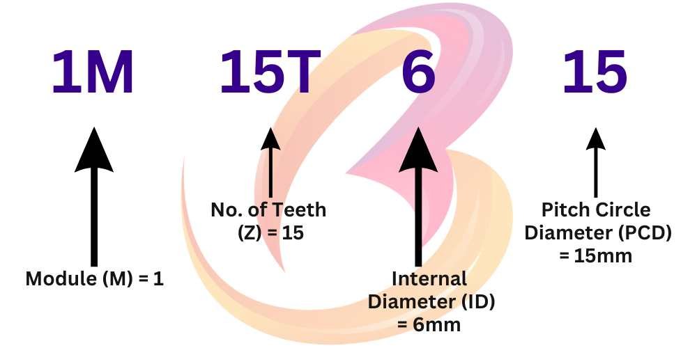
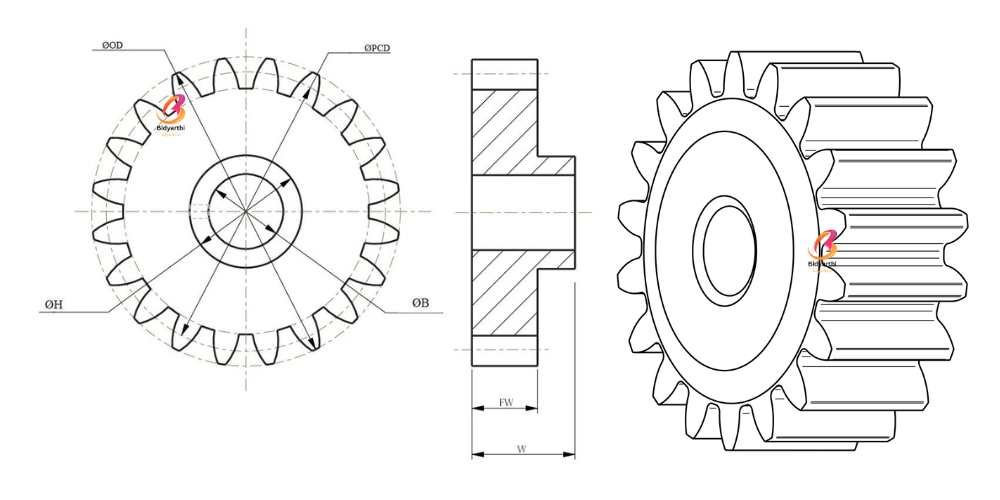
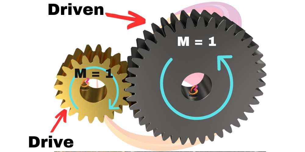
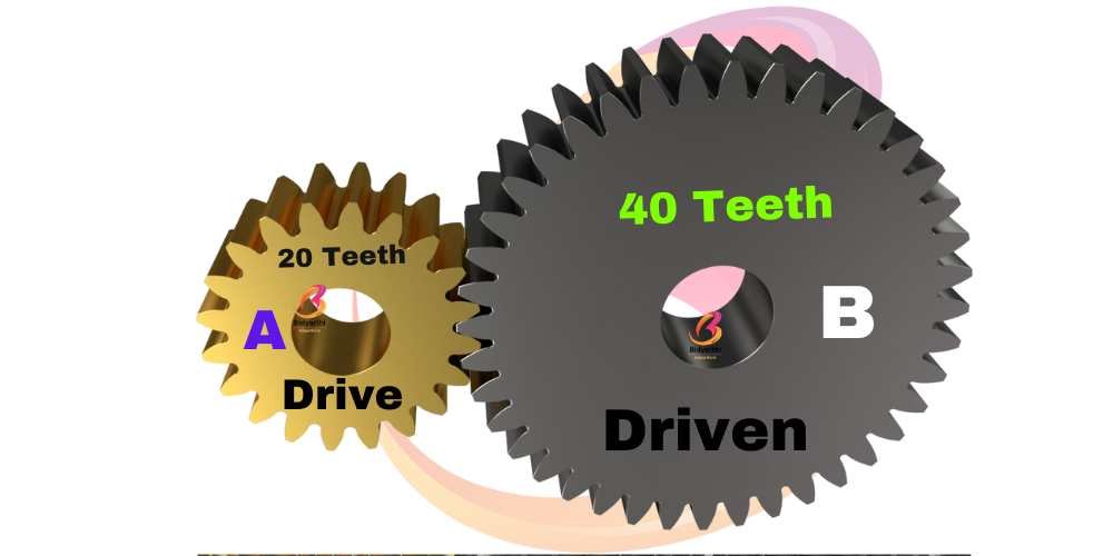
4. Pitch Circle Diameter (PCD):
PCD is also important to be considered while selecting Gears because it decides the distance between Drive and Driven Shaft. A pair of gears should mesh in such a way that their reference circles which are also known as PCD are in contact, the centre distance (a) is half the sum total of their reference diameters.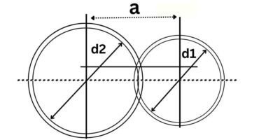
Center distance (a) a = (d1+d2) / 2
So, “a” will be the distance between two Shafts on which Drive or Driven Gears to be mounted